Cutting and Etching Vectors from Rhino5
In this tutorial we will cover how to laser cut and etch vectors from Rhino5 on a Trotec Speedy 300 laser cutter. While this laser cutter is capable of using input from a variety of software, CAD software such as Rhino or AutoCAD is preferred.
If you are not using Rhino and would like to skip to Trotec Engraver Properties, Focusing the Trotec, or Job Control click the appropriate link.
If you have not already done so, please read through the rhino training manual. Chapters 1-4 should be enough to get you started, chapters 5 and 6 are recommended.
Draw your geometry into the file, or import it from another rhino or CAD file then nest it as best as you can, minimizing waste area. You should draw your measured material size on the orange positioning layer. This will allow you to visualize where waste area is located for testing. In this case the material was 12 inches by 4 inches.
Use the dFab_Trotec.3dm file as a starting point at first because it has been configured to save you time. Notice that in this file the layer print width is set to 'Default' and the Display Color is defined By Layer.
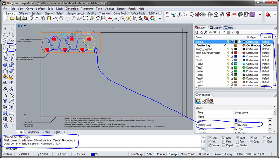
Type in print then a space or Ctrl+P. Rhino's print dialogue will begin.
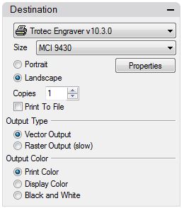 |
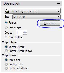
Choose the Trotec Engraver The size should default to MCI 9430 in this window. If not, that's cool don't worry. Choose 'Landscape' We want 'Vector Output' and our Output Color should be 'Print Color' |
|
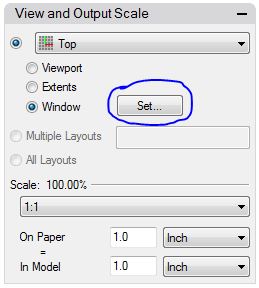
Top Viewport should be default. If not, go back and print from the Top Viewport (if you did infact draw your work on the xy construction plane). The scale should say 100% and 1 inch on paper = 1 inch on the model. Last, click the 'Set...' button. The print window will disappear and you will be able to move the print window around in the active viewport. Read ahead before you move the window. |
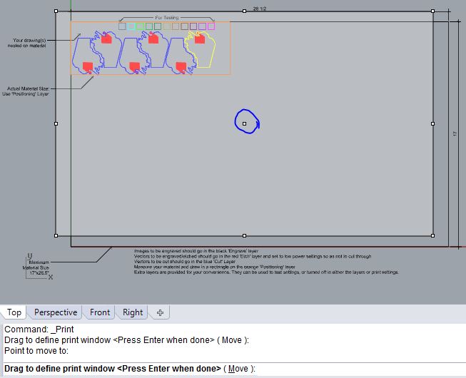
Here you will be able to move the window around by clicking on the point in the middle and dragging the print window. All that matters here is that your orange positioning rectangle, the actual material size, is inside of the print window.
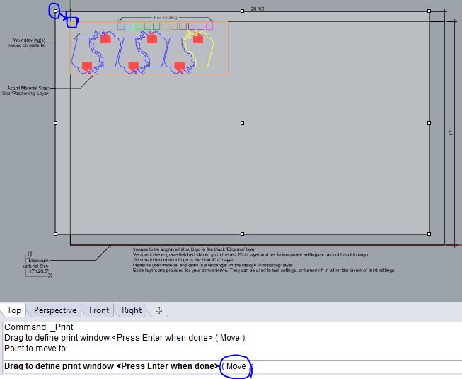
If you need to have the print window alligned perfectly, you can click Move on the command line and snap the top left hand corner of the print window to the top left hand corner of the 28.5 x 17 inch rectangle.
Once the boxes are aligned, hit enter, or space bar or right mouse click and you will be returned to the print dialogue.
|
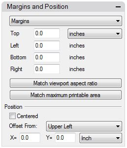
Everything here should be set to zero. |
|
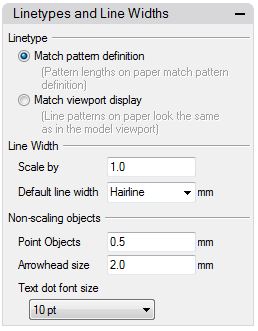
Linetype: Match pattern definition. Default line width must be set to Hairline. The laser will be confused with any input other than 0.001mm or 'Hairline'. Choose Hairline if it is an option. |
|
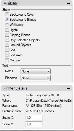
Make sure 'Locked Objects' is unchecked or that you deleted the 'Layout' layer. I leave background bitmap checked because that is one way to print images. This will be discussed in a later tutorial. X and Y scales should be set to 1.0 |
|
Scroll back to the top and choose the properties button. Now we can edit the driver settings for the printer, allowing us to configure the laser cutter in a way that is appropriate for our file. |
Trotec Engraver Properties
|
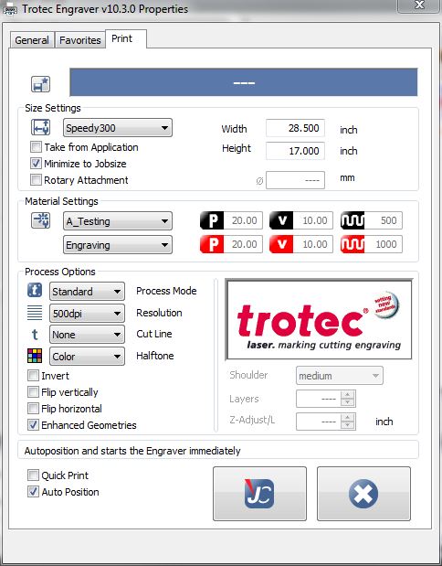
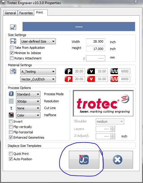
Size Settings: Process Options: Under Halftone, Color must be selected if you would like to define power settings by layer for text or hatching Enhanced Geometries is a good choice if you have arcs in your file. Auto Position |
|
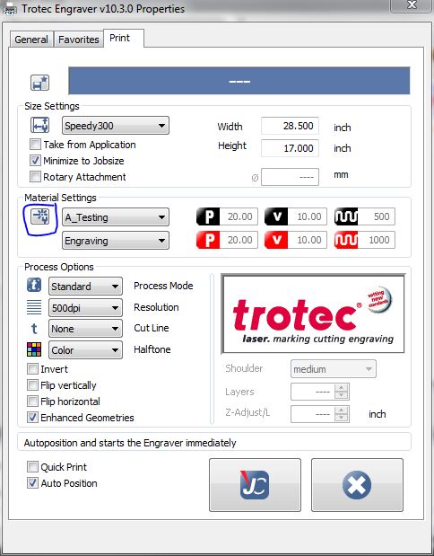
The settings to the left are the standard configuration for cutting and etching vector geometry as well as raster engraving text or hatching. Now click the circled 'Material Database' icon The Material Database will now open. |
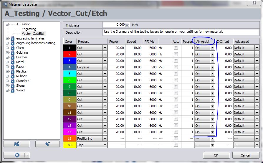
Your window will likely look a bit different than this, and that's OK. I want to stress a few points here.
- Air Assist should be turned on. Please double check this each time you open the Material Database
- Z offset will move the table up or down (positive numbers move down) from the focused position.
- A good starting point for PPI/Hz is about 6000Hz for cutting and vector etching and 500PPI for engraving.
- Notice that we have the red layer set to 'cut' even though we will be etching. We will accomplish this by lowering the settings so as not to cut through. This is the fastest way to etch vector graphics onto your material.
- We will be able to edit these settings again from within the Trotec Job Control software after we print from Rhino.
Press the 'JC' button to store your settings, then press print on in Print Setup.
Focusing the Trotec
Now it's time to turn on the laser cutter and extraction fan.
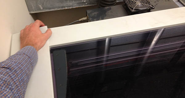
The machine power switch is located on the back left corner. Toggle that on. It will automatically find x, y and z home so long as the lid is closed.
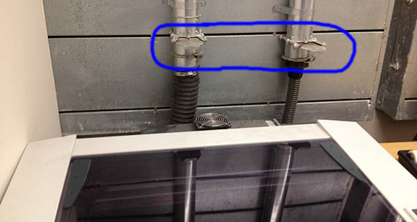
Next make sure the gates are open.
 \
\
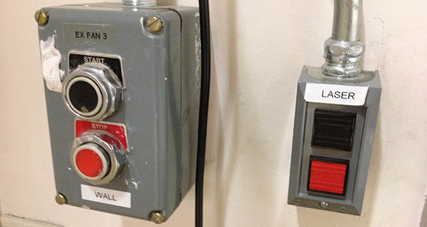
And turn on the extraction fans. They are located around the corner to the right as you are facing the laser booth. The switch on the right that says laser must be on for all laser cutting. Turn the one on the left on if you are cutting acrylic sheet or other approved plastics.
|
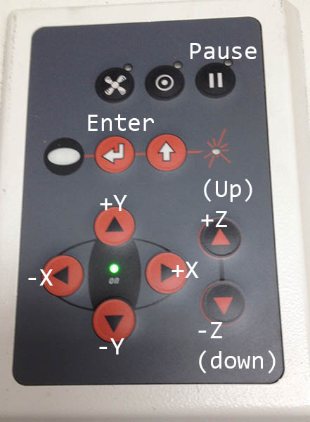
This is the controller for the X, Y and Z motion on the machine. Pressing 'Enter' after your job is complete will repeat the job with the same settings. 'Pause' will pause the cut after it completes the current block of code. Lifting the hood or lid will turn off the laser. If there is an emergency, lift the hood and move the flaming material to the white 'burn bin.' |
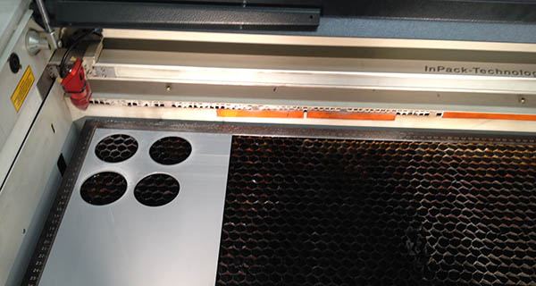
Use the keypad to move the table up, about 2 inches away from the cutter head. Move the cutter head with the X, Y keys onto an unused portion of your material.
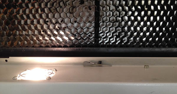
The Z focusing tool is located on the ledge inside the machine.
Hang it on the cutter head as you see here.
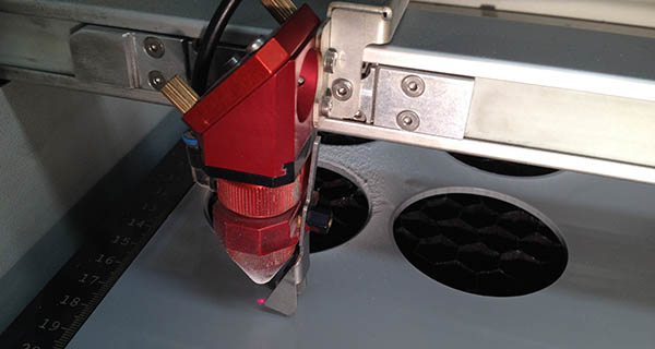
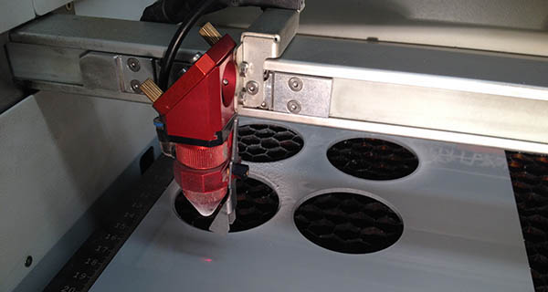
Move the bed up again, until it is close, as shown above. Now move slowly up one click at a time until...
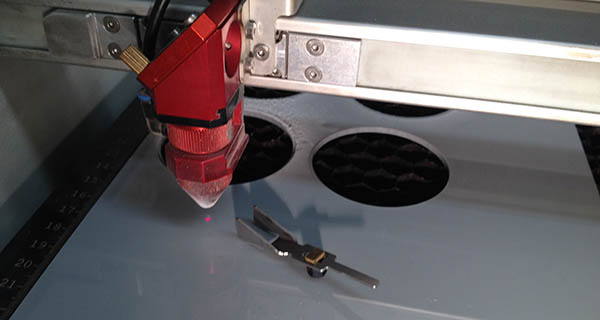
The focusing tool falls off.
Be sure to put the focusing tool back where it belongs and close the lid.
Job Control
After drawing the measured material into your file on the positioning layer, nesting your geometry, configuring the Print Settings and focusing the machine, you are ready to cut.
Press print and Job Control should open up, it may be flashing on the task bar.
If you are not sure about your settings, please refer to the page on Testing Settings.
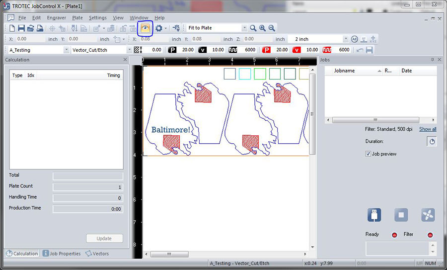
You will probably see a gray box with the file name appearing in the middle somewhere instead of what you see here.
Click ![]() or press Ctrl+I to see your geometry.
or press Ctrl+I to see your geometry.
The next step will be to connect to the printer. Click ![]() or press Ctrl+L. After connecting you may notice that the laser is represented on screen with cross-hairs. You can snap to this, but it is not necessary in this example.
or press Ctrl+L. After connecting you may notice that the laser is represented on screen with cross-hairs. You can snap to this, but it is not necessary in this example.
Finally before cutting you should verify your power settings. Click ![]() or press Ctrl+M.
or press Ctrl+M.
If you are not sure about your power settings, or need very accurate settings, for example to cut white mat board with minimal burning, you should refer to the Trotec Test Settings tutorial.
You cannot always trust the power settings saved in the Material Database. They are a good starting point, and many times will work, but please test settings before running a long job.
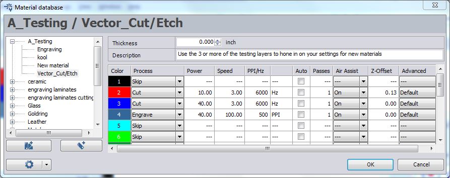
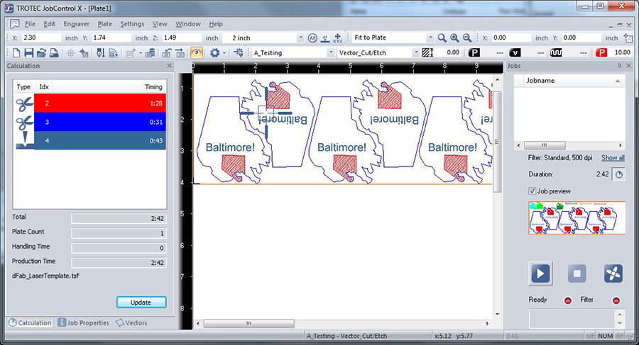
Above are the settings used for this file. The machine will process 'Engrave' first then both 'Cut' opperations following layer order. For example, this file will cut color 4, then 2 then 3. At 2 the machine will change the z offset to 1/8 inch. This creates a slightly heavier line weight which can be nice for etching. Finally it will cut the perimeters which are on the blue layer.
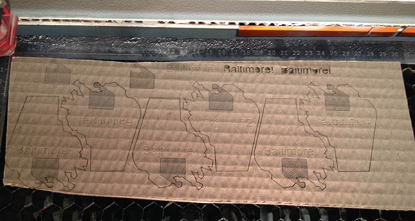
And this is how it looks completed.