
Access
We have developed a comprehensive manual compiling years of experience and dozens of sources into one place. All answers to the questions on the certification tests 1 and 2 are found in the PDF manual. Level 3 has questions that would be answered by working with McKibbin at the machine.
CNC Level 1
Students must complete this prior to using the CNC outside of class time while enrolled in a course that teaches how to use the CNC.
CNC Level 2
Students who want to work with the CNC in the semesters following the course in which they were trained must pass this level 2 test.
CNC Level 3
All instructors must achieve Level 3 prior to proposing coursework that teaches CNC in dFab. Level 3 means you can run the CNC when McKibbin is not in the building.
FANUC
XYZ dimensions: 49”x97”x12”
Spindle: 12hp | 6000rpm - 24000rpm
Feed Rates: 600ipm Cutting | 1000ipm Rapid | 2000ipm Max Rapid
Vacuum Table: 6 zones 10hp, Pod Ready
Tool Changer: 18 tools
File Name: Up to 32 characters
Controller Notes
ScreenShot
Press and hold the [SHIFT] key until the system clock stops. The screen capture will be written to the set USB memory device (17 on I/O Channel).
Custom Macro Notes
Haas VF-1
XYZ dimensions: 20”x16”x20”
Spindle: 30hp|50rpm-8100rpm
Feed Rates: 650ipm Cutting|1000ipm Rapid
Table: (3) 1/2-13 T-Slots|3000lb weight limit
Tool Changer: 20 tools Max weight 12lb
File Name: Onnnnn (first comment is user readable filename)
Haas
Control Tips | Operators Manual
Controller Notes
ScreenShot
[Shift] + [F1] (will save capture to USB if available, hard drive if not)
filename + [Shift] + [F1] (will save capture to USB with a file name)
Save a copy of the current program
onnnnn + [F2] will create a copy of the current program
Save a program created in the MDI
[HOME] then onnnnn + [ALTER] will save the current program in memory
Zero "Distance to Go" Values
Current mode: HANDLE JOG + POSITION
Press: EDIT or MENU
Press: HANDLE JOG
All axis now zero on DIST TO GO
Zero "Operator" Value(s)
Press: HANDLE JOG, choose unit and axis
Press: CURRENT COMMANDS + PAGE UP until large digit display is shown
Jog to Operator zero location, one or more axis at a time
Change axis or units to get close
Do one of the following:
- Press: ORIGIN -- Operator value of active axis will become 0.0000
- Press: X, Y, or Z + ORIGIN -- to change jog axis and zero new axis
- Press X, Y, or Z + number and ORIGIN -- To insert a value other than 0.
Change "Work Zero Offset" Value From Text Buffer
Use OFFSET to make "Work Zero Offsets" active
Use directional keys to highlight the value you want to change
Enter the new value and press F1
To add or subtract from the current value, press ENTER
Set Multiple Work Zero Offsets at Different Heights
Set the dial indicator at about 15 degrees
Find Z zero on gauge block
POSITION - Position - Operator screen should be white
ORIGIN, to zero operator value
Jog to first work zero (Z only)
Zero indicator on vice or other work zero location
Press OFFSET 2x and highlight Z value on first work offset
Enter OPERATOR value and press F1
Setting 36 - Program Restart
Set on and Haas control will scan program for all needed codes and activate them before starting mid-way through file. We always leave this on.
G83 IJK
G83 I1 J.5 K.25;(good starting point for .25" drill bit)
Rule of thumb
:I=4xd, J=2xd, K=d
Content
Cut Direction
- Inside - counterclockwise
- Outside - clockwise
Travel Speeds
- Correct = No Dross, 20 degree trial of molten metal.
- Too Slow - wide cut, dross is easier to remove
- Too Fast - sparks off top, hard to remove dross, not completely cut
Torch Height
- Torch to work distance is too high if dross is on top
Lab computers run startup scripts which automatically copy some files where they need to be on your hard drive when you log in. Paths to the server are included below in case the startup script doesn't work.
The example file used below is available on the server if you would like to follow along. Make a local copy of the Cradle-CAM-Empty.3dm file on your desktop.
\\picasso\Courses\_Student Resources\dFab\Resources\CNC\FANUC - CNC Router\Examples
Setup
- Maximize your rhino window. Take the time to configure things so you are not wasting screen real estate.
- From the menu bar, choose RhinoCAM 2020 > MILL
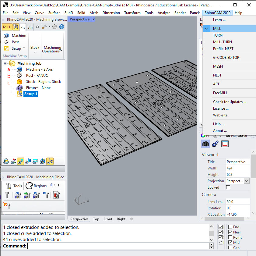
Once you choose Milling, two panels will appear, the Machining Browser (top left) and the Objects Browser (bottom left). They are dock-able like other panels in Rhino. Take a moment to configure your workspace. If you have room on your screen it is advisable to make the panels wider than shown above. In the Machining Browser,- Choose "Machine - 3 Axis," this means we will be cutting using three linear axis of X Y and Z (with no rotational axis of A, B and C).
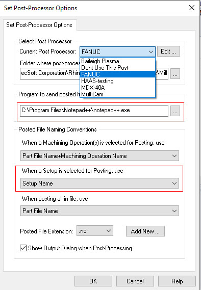
- Right click on "Post" to select the machine for your application. In our example, choose FANUC.
If you are seeing a different list of machines, try this location :
\\picasso\Courses\_Student Resources\dFab\Resources\Rhino\RhinoCAM\Posts
Also on this window, change the program to send posted files to Notepad ++
C:\Program Files\Notepad++\notepad++.exe
Finally, change "When a Setup is selected for Posting use" to "Setup Name" and click "OK"
- Select your extruded stock in the perspective viewport and right click on " Stock", then choose "Stock from selection
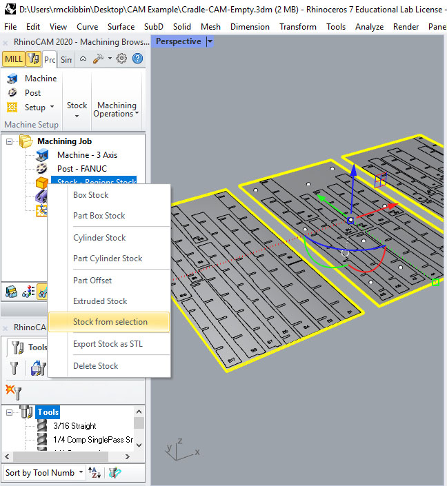
In this example we are using 3/4" plywood, which is always drawn at 0.70" thick. This is just a 48" x 96" rectangle drawn on the construction plane and extruded down 0.70". Here we needed three pieces of stock to fit all of our parts.
- Now set a work zero. This is where we tie a location in our model to zero on the machine. In our model, it is the near left bottom corner of our stock.
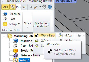
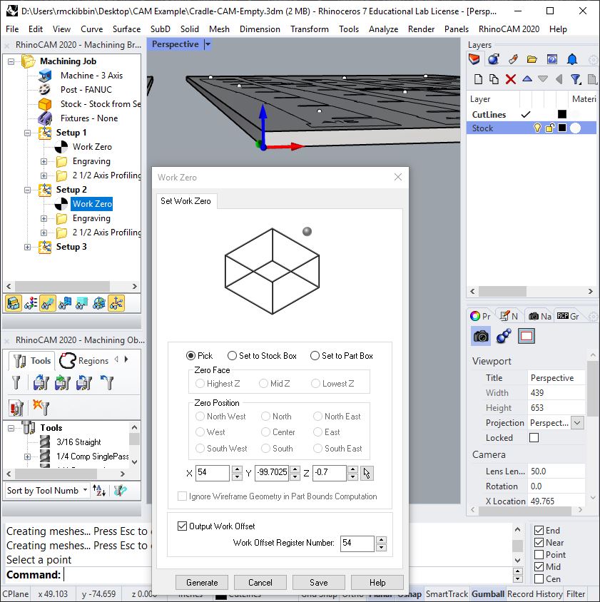
With Setup 1 selected, choose Work Zero from the Machining Operations menu
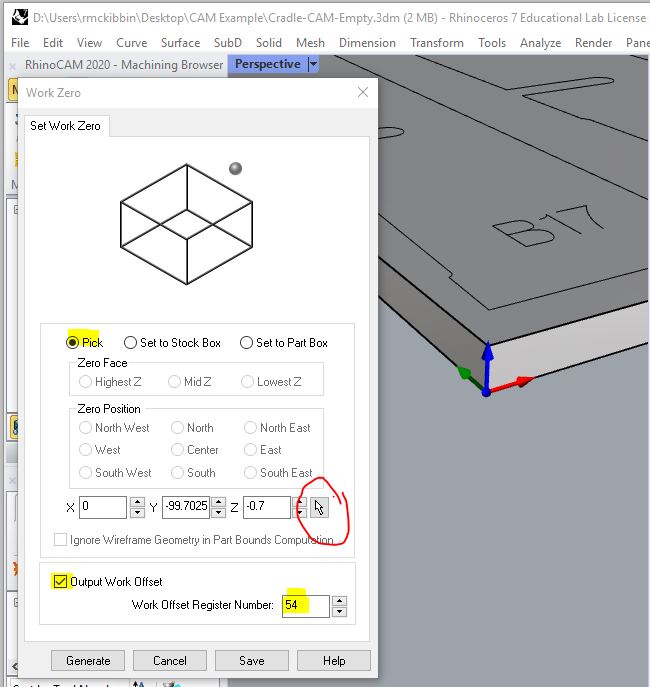
Next choose "Pick" and use the circled pointer button to choose the work zero from the modeled stock using "End" Object Snap. The values for X, Y and Z will update after your selection as shown above. Double check that Z is correct, -0.7" in our case. Choose your work offset, G54 is the one we are using here. Click "Generate."
- Now turn off your stock layer and maximize the Top Viewport. All input geometry that will be used for toolpathing is on the XY plane. The Work Zero is at the bottom of the stock on the near left hand side.
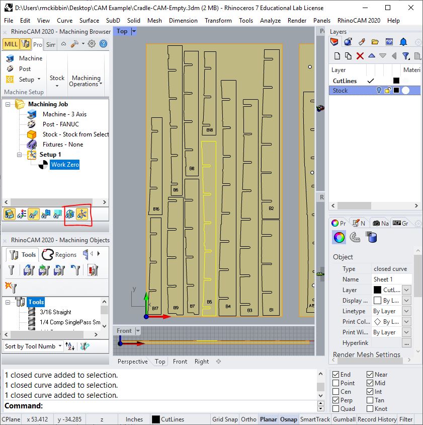
Notice the buttons at the bottom of the Machining Browser, especially the two circled in red. Keep the right one on and the left one off.
- Choose the Load Tool Library button squared in red below, then select an appropriate tool library.
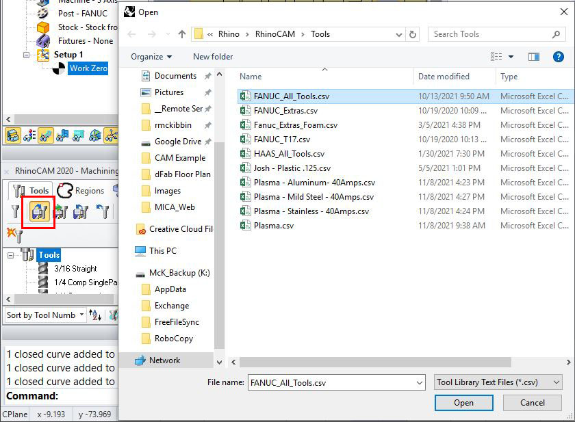
For our example, use the Fanuc_All_Tools.csv library. Notice that we are using *.csv files here. You may see a blank screen if you have *.vkb selected. They are located on the server here:
\\picasso\Courses\_Student Resources\dFab\Resources\Rhino\RhinoCAM\Tools
Understanding 2d toolpaths is essential in order to achieve machining goals. Three types of toolpaths cover the majority of operations, Profiling, Pocketing and Engraving. We will cover profiling and engraving here. Pocketing is the same as profiling except it removes all material inside, or between two, curves. All toolpaths can be used to cut through or partially through your part.
You may have noticed that we are working down the items in the Machining Browser. The program sent to the machine (gCode) that you are currently writing will be read from top to bottom. Each step in the Machining Browser will be executed top to bottom as it is translated using the Post selected earlier to create your gCode. Things at the top happen before things below them.
Each sheet of plywood will be associated with a Setup containing a Work Zero and one or more Tool Paths. Each Setup will be posted to create separate gCode files to be executed at the machine, one per sheet of plywood. Each Setup, containing its own Work Zero and Tool Paths, will be sequenced by you the programmer. Program the first sheet, run it on the machine to verify, then copy and paste the setup to program the other sheets efficiently.
Engraving
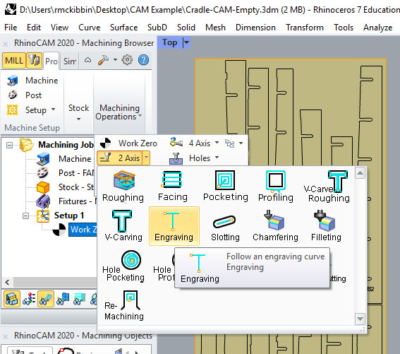
With the Work Zero selected, choose an Engraving Toolpath.
We will work from left to right through the bottom row of tabs, then left to right through the top row of tabs.
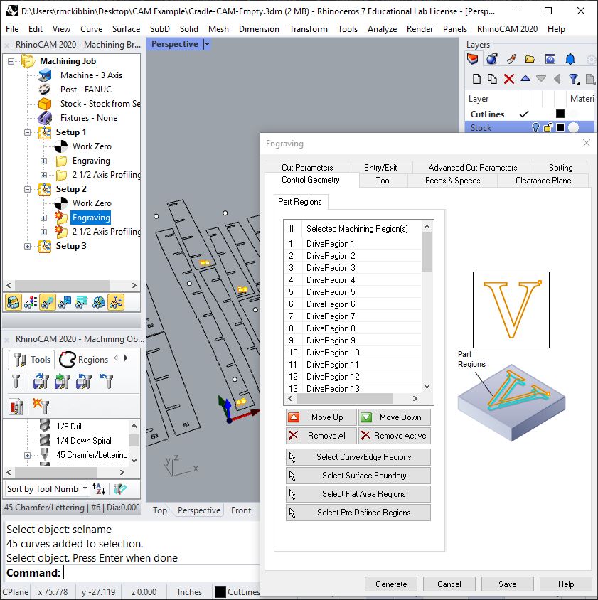
Control Geometry
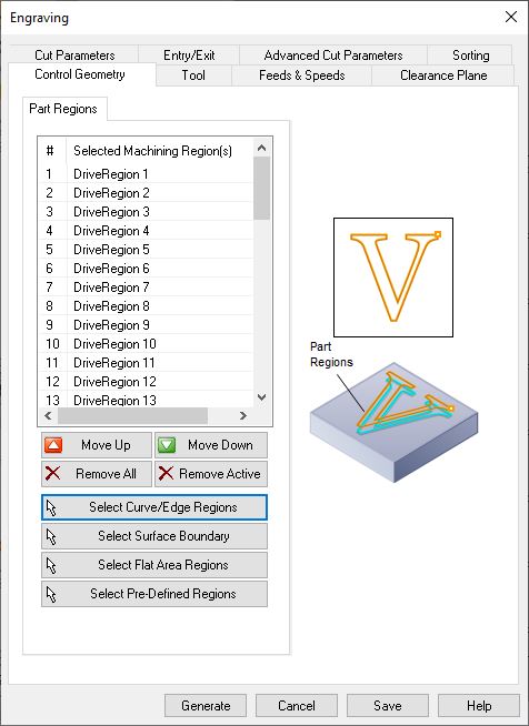
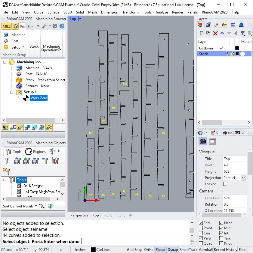
Use the "Select Curve/Edge Regions" button to choose the drive regions for engraving from the Rhino Viewport with LMB Clicks.
Each of these will be cut in the order which they are selected, unless a sorting override is chosen in another step.
Tool
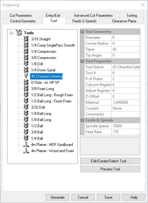
Choose the 45 Chamfer/Lettering tool. Ball mills also work well for engraving, but have a heavier line weight/depth ratio.
Feeds & Speeds
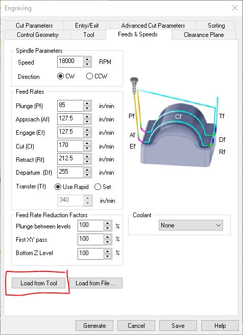
Click "Load from Tool." This ensures that the settings are for the currently chosen tool on the previous tab and not from some other tool or preset.
Clearance Plane
The clearance plane is the height above your material that the tool will go to before it rapidly moves to the next cut. This would need to be increased if the workpiece is warped to avoid a collision.
Another common issue is a very high clearance plane if CAM work is being done in the design file. We recommend exporting cut-sheets to a new file named ProjectName-CAM.3dm after creating them in the design file to avoid this and other CAM issues.
![]()
In general leaving Clearance Plan Definition set to Automatic is sufficient. Other options may be discussed with your instructor if it is not.
Keep "Cut Transfer Method" set to "Clearance Plane" unless otherwise instructed.
Cut Parameters
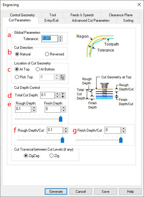
- Tolerance is how far the toolpath can deviate from the degree 3 NURBS curves you have in Rhino. Degree 2 will be translated to circular moves, degree 1 are straight lines already.
- Reversing cut direction is possible, but usually not needed because we are centering the tool on our input curves.
- We are cutting down, below the xy plane, from our input geometry (on the xy plane) to a prescribed depth. This is designated as "At Top." and is the most common way we work in dFab. "At Bottom" will use the input curves as a floor to cut down to.
- Total Cut Depth, the final desired depth of cut, is broken into two strategies, Rough and Finish. Rough material removal strategies use aggressive depth and step-over. They not very accurate due to tool deflection and tear out. Finish material removal strategies are precise and gentle on tooling to avoid tear out and tool deflection.
- Use Rough Depth and Finish Depth to describe how much of the cut you want to use an aggressive strategy.
- Use Rough Depth/Cut to define how aggressive to go.
- Use Finish Depth/Cut to define how much material should be left for careful removal in the last pass.
Here we are using a 0.100 single pass to tag our parts. This is a pretty deep cut for this purpose, for easy identification of jig parts. Lightly taging parts is also possible with cut depths of down to 0.01 or even 0.001 depending on the precision of your workpiece.
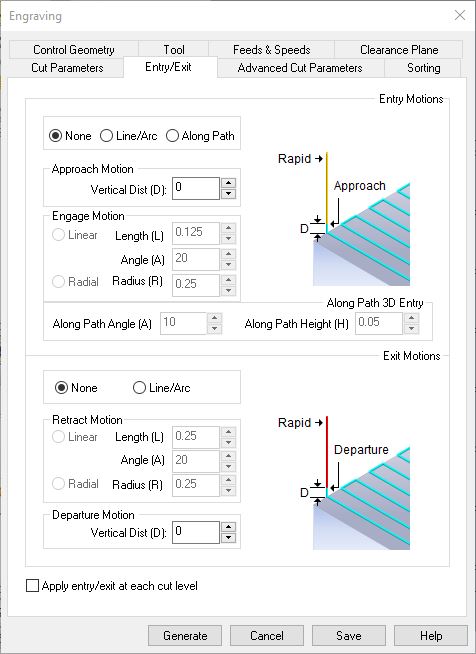
Entry/Exit
Both Entry and Exit motions can be set to None.
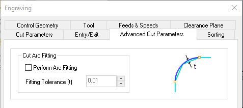
Advanced Cut Parameters
Un-check "Perform Arc Fitting"
Sorting
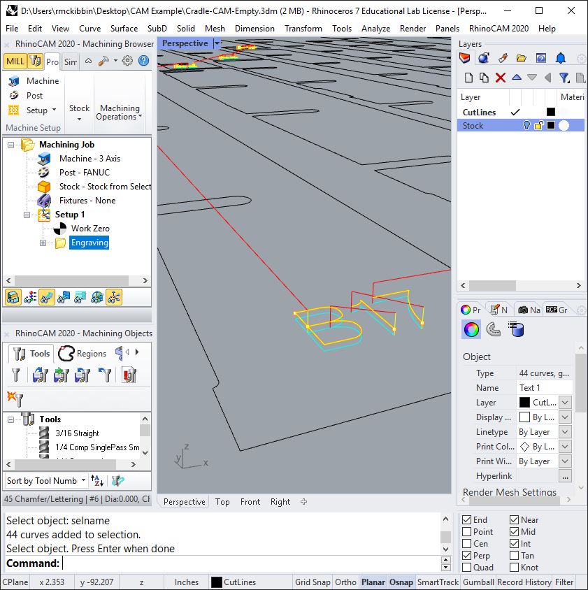
RhinoCAM should sort in the order curves are selected from the viewport. We have noticed a bug where if you choose something other than "No Sort" the sorting will stick and not return to the original selected order or that the order objects are selected is not recognized and automatically sorted anyhow.
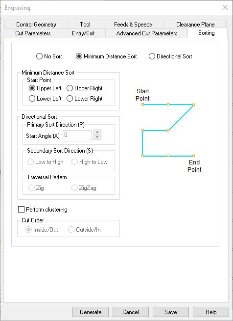
I lied earlier and used _SelName to select the input curves for this demo... so I want to sort them automatically. Here we use "Minimum Distance" from the "Upper Left" hand corner. Knowing the cut order will help us know how far along we are while executing the file on the machine. In this case, the toolpath is complete when it reaches the front of the sheet.
Generate
OK, that's it! click "Generate" and you have created your first engraving toolpath!
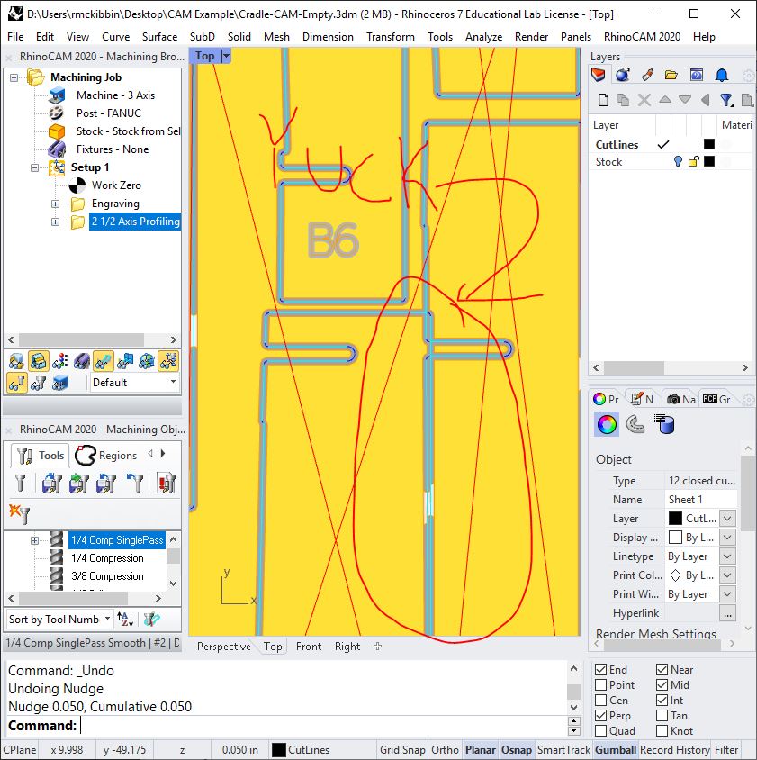
Notice that if we change any of the inputs used for our toolpath, RhinoCAM will notify us with a red firework icon on the folder containing the toolpath. Below, I moved the input geometry to break the toolpath.
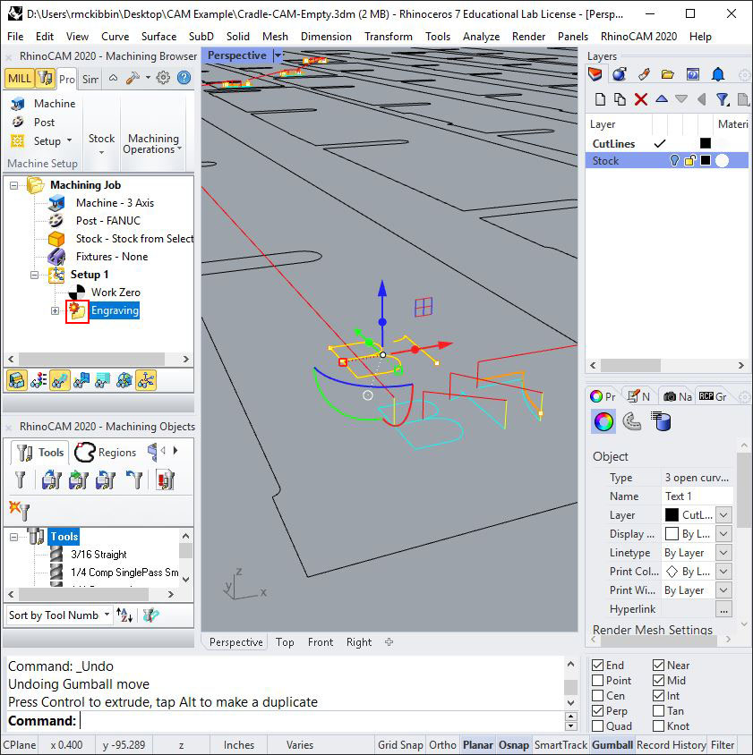
If you want to make that change, such as move geometry once a toolpath is created, Regenerate the toolpath by right clicking on the firework folder icon squared in red. The toolpath will update to match the moved input geometry.
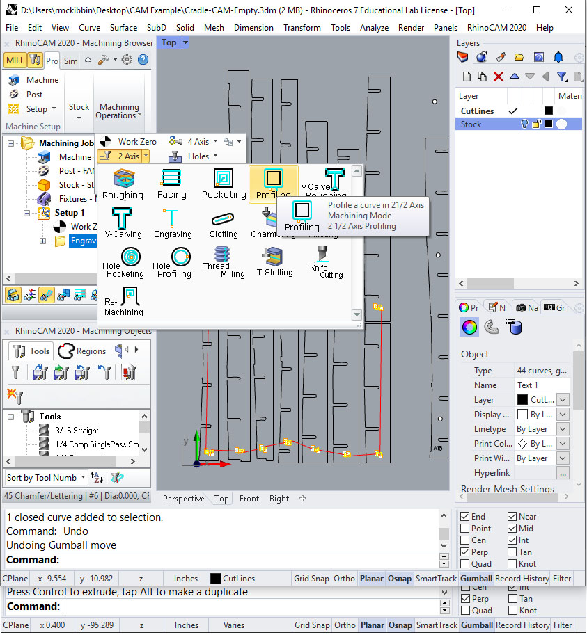
Profiling toolpaths are used to cut a shape to its final size, the size it was drawn. The software uses the tool diameter and input geometry to guide the toolpaths, maintaining the correct offset for the selected tool. This allows the programmer to change tools without re-drawing. The programmer can also adjust for variations caused by material thickness and tool deflection. This way we can draw our slots at 0.7" but cut them to 0.713" or 0.695" depending on the actual thickness.
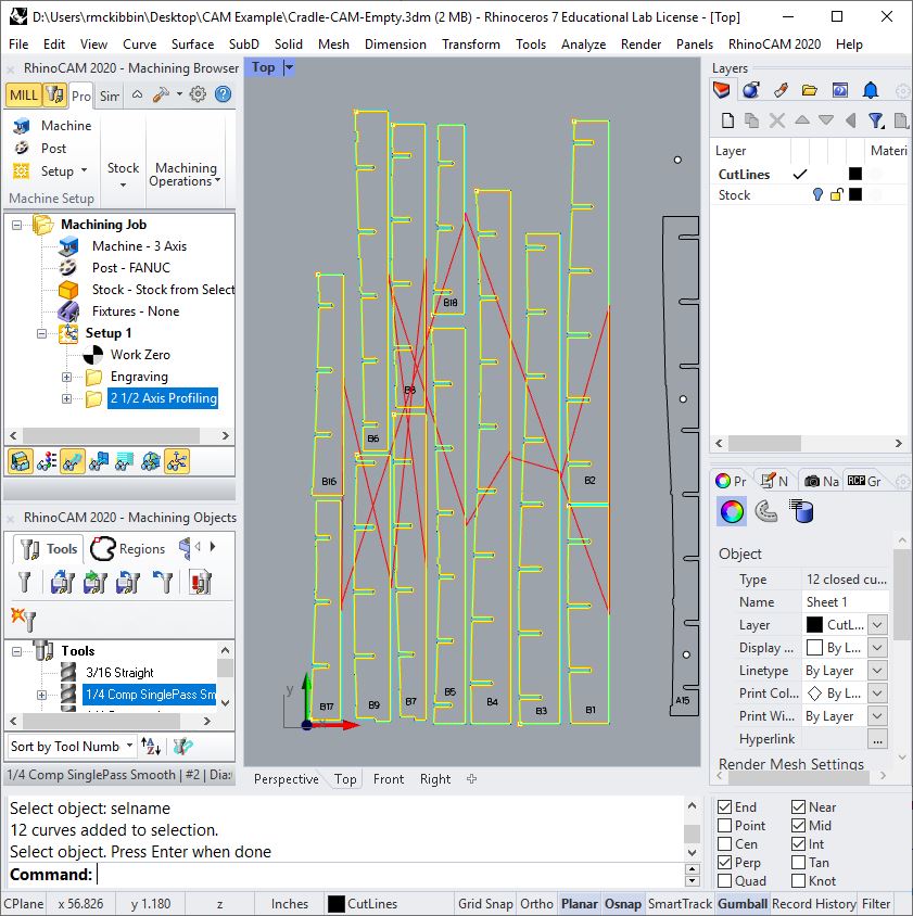
With the Engraving toolpath selected, choose a Profiling toolpath.
Control Geometry
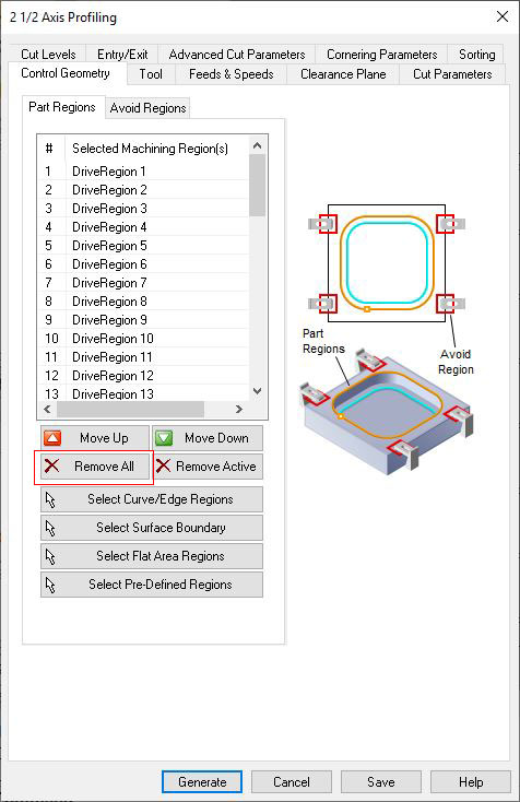
If there are pre-selected regions you may need to use the "Remove All" button before "Selecting Curve/Drive Regions."
Tool
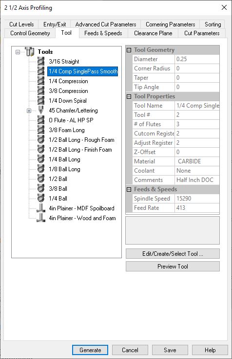
Use the 1/4 Compression tool.
Feeds & Speeds
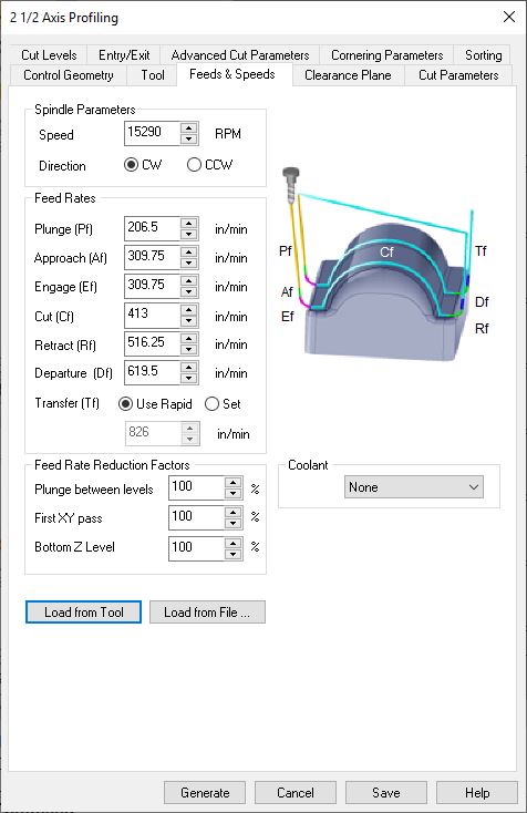
and load the settings from the tool.
Cut Parameters
The settings on this page affect changes that can be seen while looking down on the part.
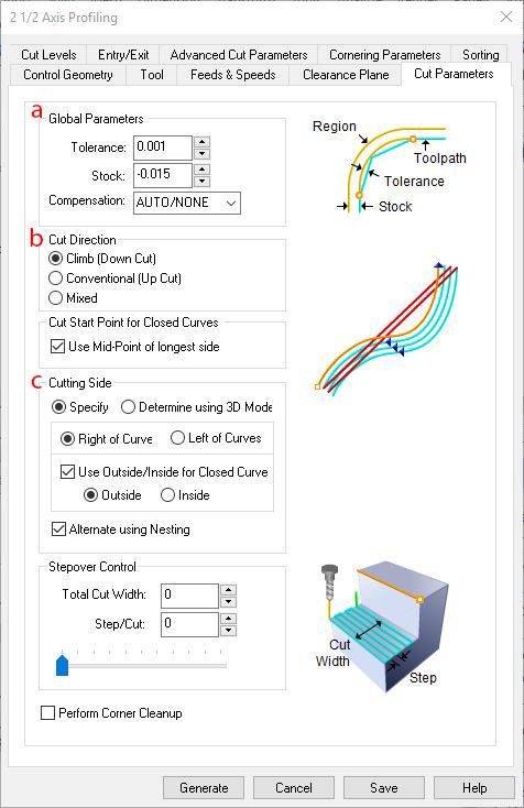
- Global Parameters
- Tolerance is equal to your model tolerance, or 0.001 for our shop.
- Stock. This value is the distance from the edge of your tool to the edge of the control curves in this toolpath. When set to zero, the cutting edge would theoretically touch the control curve. This is not the case due to real world cutting forces. Stock values in the range of -0.006" to -0.01" from the measured material thickness will usually yield a good fit when climb cutting. The example material measured 0.71" thick and was drawn at 0.70," a 0.01" difference. Dividing that by two, for both sides of the slot, and adding our allowance for slip, we get -0.015" for the Stock value.
- Compensation allows for G40 or G41 tool radius compensation on the control. This is an advanced feature and is usually best set to AUTO/NONE. This feature is enabled for both our FANUC and Haas machines.
- Cut Direction
- In climb cutting, the tool rotates toward the workpiece, cutting forces deflect the tool away from the line. This is usually preferred on CNC equipment and is the setting we will use.
- Conventional cutting is used when using a hand held router, or on machines that have Acme thread such as a Bridgeport knee mill. The tool deflects slightly toward the control curve in the high forces involved in CNC machining.
- Mixed cutting forces alternating climb and conventional.
- Cutting Side
These settings determine which side of the control curve to draw the toolpath. The settings shown will work correctly for most scenarios. Inspect the cyan and blue toolpath lines after generation to verify that cuts are being made on the intended side of control curve. Any issues can be resolved by un-checking "Alternate using Nesting" and "Use Outside/Inside for Closed Curve" then using the _Flip command in rhino to reverse the direction of input curves as needed.
Cut Levels
The settings on this page affect changes that can be seen while looking at the part from the side.
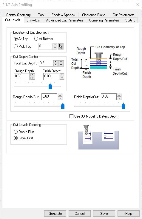
- Location of Cut Geometry
- We are cutting down, below the xy plane, from our input geometry (on the xy plane) to a prescribed depth. This is designated as "At Top." and is the most common way we work in dFab. "At Bottom" will use the input curves as a floor to cut down to.
- Cut Depth Control
- Total Cut Depth, the final desired depth of cut, is broken into two strategies, Rough and Finish. Rough material removal strategies use aggressive depth and step-over. They not very accurate due to tool deflection and tear out. Finish material removal strategies are precise and gentle on tooling to avoid tear out and tool deflection.
- Use Rough Depth and Finish Depth to describe how much of the cut you want to use an aggressive strategy.
- Use Rough Depth/Cut to define how aggressive to go. Our tools are setup to cut up to 3x the diameter in one single pass. A 1/4" tool can cut 3/4" in one pass with appropriate work holding.
- Use Finish Depth/Cut to define how much material should be left for careful removal in the last pass.
- We have chosen to leave 0.08" or eighty thousandths for the finish pass.
- Cut Levels Ordering
- Depth First will cut through each piece in the cut order, Part B12 will be fully removed from the sheet before moving to B13.
- Level First will cut to the first depth, -0.63 from the top of the stock, on all parts, leaving them connected to the sheet and preventing loss of vacuum hold down forces. Next it will cut through the sheet around each part. when it does so we are only removing 0.08" of material so it's not an aggressive cut, therefore the necessary vacuum holding forces are lower. This is usually the better option for our needs.
Entry/Exit
In nested sheets, like this project, along path entry is used to help lower cutting forces on our tooling.
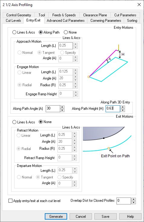
The angle for wood is 30, for steel it is 1-2 and for aluminum it is between 2-5. The along path height is always the Rough Depth/Cut value from the Cut Levels tab. If you used more than one pass in Rough Depth/Cut check the "Apply entry/exit at each cut level" box at the bottom of the window.
Advanced Cut Parameters
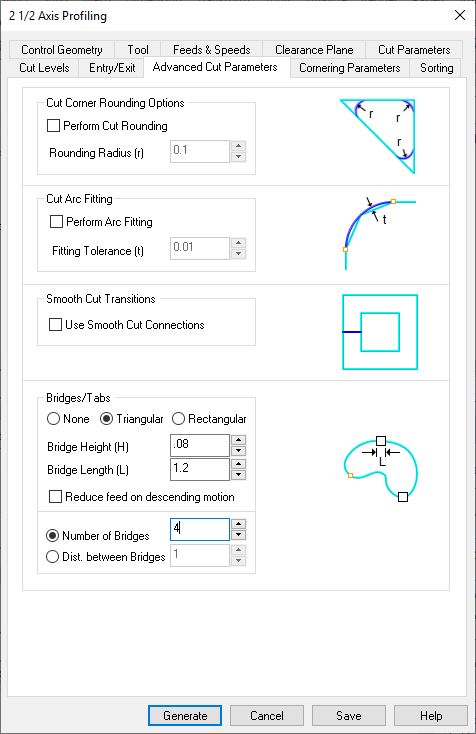
Un-check Cut Rounding and Arc Fitting for any finish passes. They are OK for roughing.
Tabs should be used for any parts that measure under 2sqft with our vacuum table, or when working with warped material. The settings above will hold securely but also break away easily. User selected tab locations can be made by creating machining regions and selecting locations through the Machining Objects Browser under the Regions tab.
The portions of 2 1/2 Axis Profiling that are not covered above are discussed in the previous section on Engraving toolpaths. Choose "Generate" and review your toolpath. Check that the Toolpath lines are on the correct side of your control geometry.
After completing setup and toolpathing, it is time to verify your operations through a computer simulation. In the days of old, programs were verified on the machine, cutting foam, wax or even air. This step allows the programmer to spot any mistakes, such as feeds and speeds, clearance plane, part location, and machine collisions to name a few. Today, the computer is a helpful tool in this verification process, our software can run a simulation.
The computer will simulate the program making the programmer aware of any collisions, which must be found and addressed. Remember that the simulation is only as good as the inputs it receives, if you are not clear with yourself it is easy to be mislead. Don't skip steps, and be precise. Collisions between the tool or tool holder and the part will show up in the simulation in red. If there is a collision in the toolpath, the firework icon will appear on the offending toolpath.
In the Machining Browser, go to the "Simulation" tab, to the right of the "Program" tab at the top. Select "Setup 1" and press "Play."
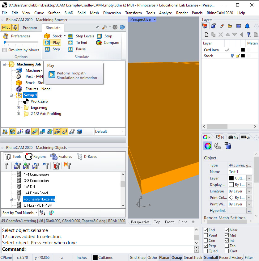
Notice that "Simulate by Moves" is unchecked and the slider is fully left. This is intentionally very slow. Working in this way is good when the programmer needs to see how the tool is cutting. It's good to pay attention to the simulation and think
- "Is this the best cut order?"
- "Will the part or workpiece come loose from the table in this operation?"
- "Do the parts look correct/Am I cutting on the correct side of the line?"
Watch the simulation in its entirety. Notice that the simulations happen for all toolpaths contained within a setup when a setup is selected, and only for the toolpath that is selected. Notice that after you make changes to and re-generate a toolpath, the simulation is lost and must be "re-played". If the first toolpath is changed, all toolpaths must be re-played to see an accurate simulation.
Inspect carefully for the toolpath of one part accidentally cutting into another part as shown below.
This can be easily
spotted when programming by noticing overlapping toolpaths. If the cyan or blue toolpath lines cross, control curves must be moved until they do not. When using tabs to hold your parts in the sheet, a 1" to 3" offset between parts is used.
Different parts will present different challenges. Teaching how to program a CNC machine is hard because the possibilities are endless. Be aware of your specific goals and the challenges associated with them.
We have now established a machining strategy, which will be used for subsequent sheets of material with similar geometry on the same material.
Between Setups In The Current File
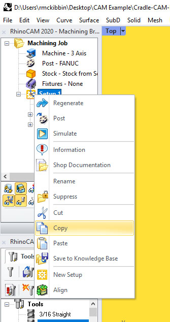
LMB select the setup, then RMB click to get the context menu.
RMB click in blank space on the Machining Browser and choose "Paste"
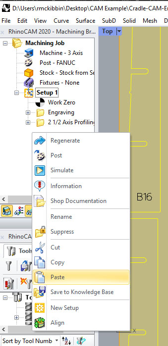
Repeat pasting the files until you have enough setups, one for each sheet in the file. Depending on how much you have on each sheet, 3 to 6 sheets per file is about the limit.
Turn on your stock layer, and set the work zero in each of the pasted setups
Associate new control geometry with each toolpath
Between Files
To copy toolpaths between different Rhino files, first LMB select the setup or machining job that you would like to copy. Then, choose "Save to KB" as shown below.
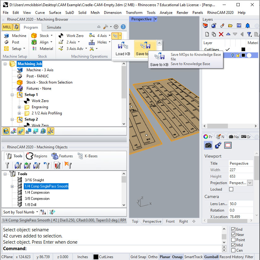
Knowledge Bases can then be loaded into another file, using the K-Bases tab of the Machining Objects Browser shown below.
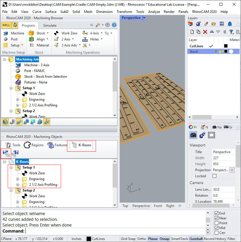
To use the toolpath, simply drag and drop from the "K-Bases" tab to the "Program" tab and associate new control geometry.
Post the File
Select the Setup for the first sheet, in our case this is named Setup 1. This setup could be renamed if desired by LMB selecting and LMB clicking on the name of the setup. The setup name is the name of your gCode text file.
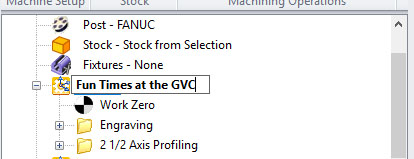
Ordinarily we leave the setup names alone. If there is a need to rename your gCode, it should be done here and not in the following steps. This will help you out down the road with troubleshooting. Good Vibes Central!
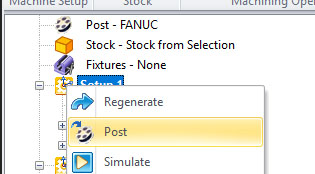
The only way to "Post" or create gCode from your toolpaths is to LMB select, then RMB click your entire setup. While it is possible to post individual toolpaths, this is not advised because it may or may not automatically contain the work zero. For dFab use, ALWAYS post the entire setup.
The Post & Save As window will appear. Select an appropriate location to save your file which could be a thumb drive (if working with the Haas or Plasma Cutter) or on the server (if working with the FANUC or Rolland). Here we are working with the FANUC.
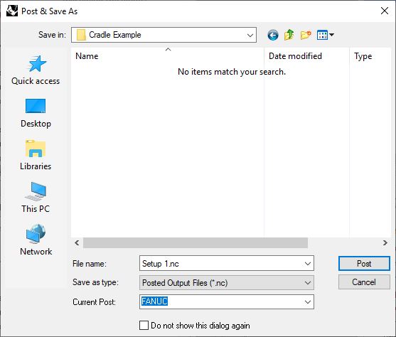
DO NOT rename your file here. Double check that the Current Post is appropriate for your machine.
The FANUC can see all files and folders inside of this folder:
\\picasso\Courses\_Student Resources\dFab\Shared\__FANUC__
You may create a new folder inside your class folder or the general folder with your name. Inside of that folder, make another folder to contain the project. For the example I will be posting my gCode to
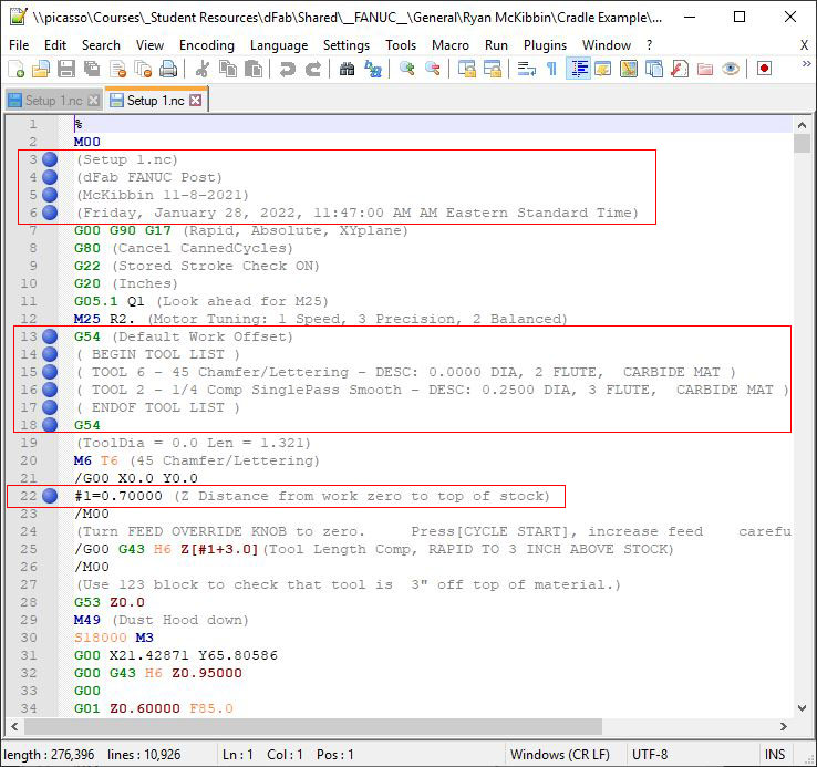
\\picasso\Courses\_Student Resources\dFab\Shared\__FANUC__\General\Ryan McKibbin\Cradle Example
Notice that the folder name is the project name, this leaves room for shorter file names (like Setup 1) to make sense.
Setup Notepad ++
After posting your file, the text editor should appear displaying the code you just programmed!
this is opening in Notepad ++ and only including the setup in the file name because of the settings we chose in
the RhinoCAM - Setup section above.
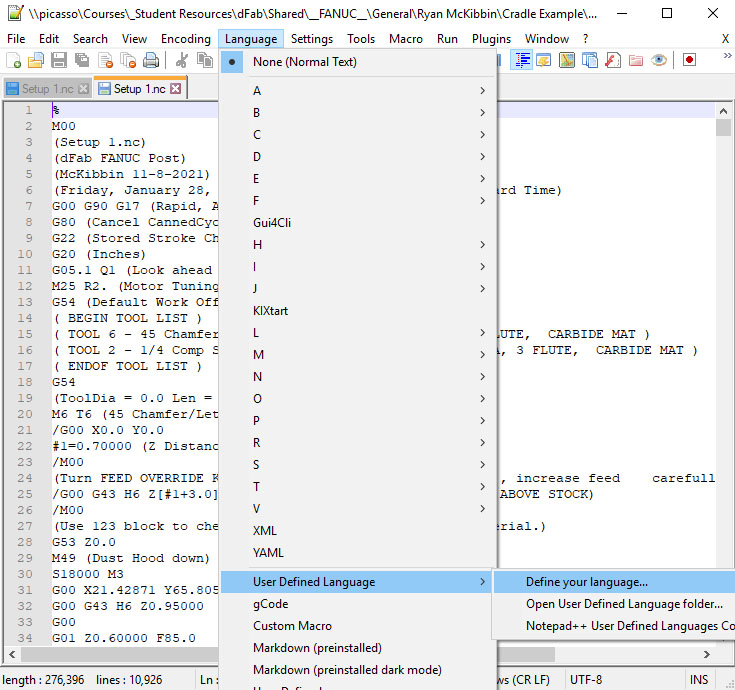
The first time you open Notepad++ it will not recognize gCode as a programming language. If you would like to add some auto-formatting for easier readability, go to Language > User Defined Language > Define your language...
Chose "Import..." button at the top left and go to this location on the server:
\\picasso\Courses\_Student Resources\dFab\Resources\Notepad++ Language
We are using the gCode language for formatting. Load this language then restart Notepad ++. You will see the languages you added as pictured above. Choose gCode. Notepad++ will automatically re-open exactly as it was left, even with unsaved documents.
Check the Code
There are 4 things to check in your gCode. They are quick, and must be checked each and every time. The first three are below.
File Name and Post Processor
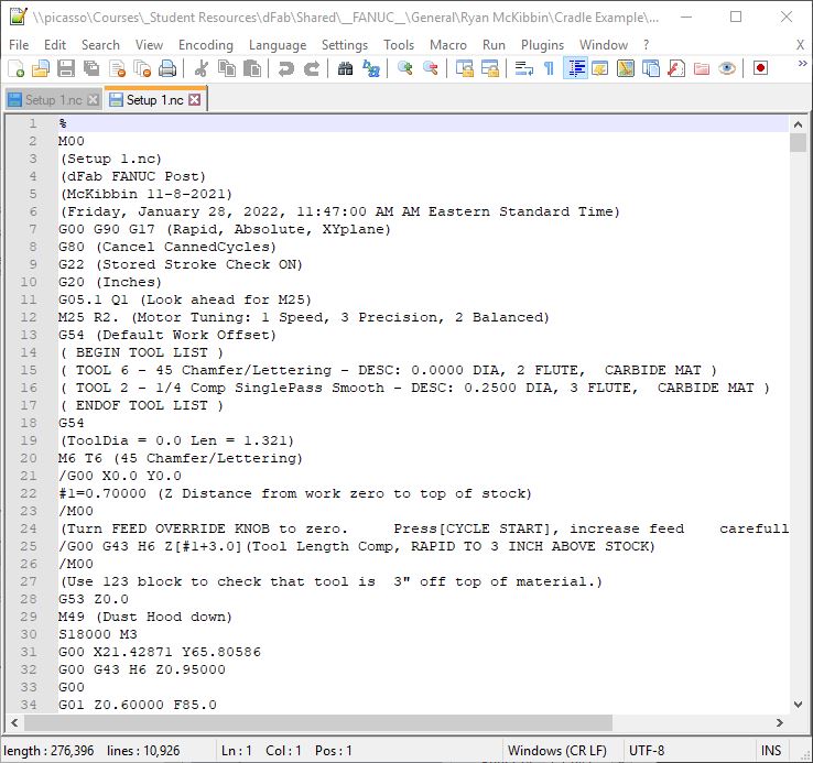
Your file name will be posted as the first comment in the file, double check that this is on line 3.
Directly below the file name, the next comment is which post processor you used. Double check that it is the dFab FANUC post, or the post for the machine that you are using. All dFab posts will say dFab and the name of the machine, also below this will be the name of the last person to edit the post and the date it was last edited.
Line 6 contains a time stamp from when you posted the file. Always post the file just before you cut and after reviewing the simulation to get your head around the project one last time before cutting.
Work Offset
The default work offset, G54 appears on line 13, just before the tool list. This work offset is included as a redundant safety mechanism and is almost always overwritten at the end of the tool list. If you used a work offset, as we did in this tutorial, look for it after the tool list, on line 18 above.
Stock Length Z
This line will look something like #1=0.7000 for 0.70 inch plywood and is located on line 22 above. The value must be the distance in Z from your work zero to the top of your stock.
When executing the file, our machine will stop and prompt the operator to check the tool length. The number stored in #1 will be added to 3” on line 25 above
/ G43 H11 Z[#1+3.0]
This makes it possible to have the work zero set to the bottom of the stock and check your work offset, tool offset and stock thickness in one step.
Advanced: If you are using offsets G57-G59 and your work zero is set to the top of your stock, then change this to #1=0.00
Last Step
Finally, we need to verify the absolute depth of cut in the file, or the breakthrough amount. How far below the work zero is the tool tip going? This can easily be done by searching the document for -Z values. Notepad++ is a powerful text editor and has a great function for checking this.
Press Ctrl + F with Notepad++ in focus
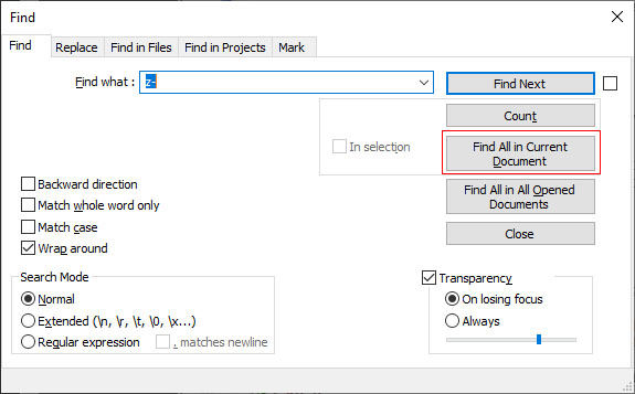
type in z- and click "Find all in Current Document"
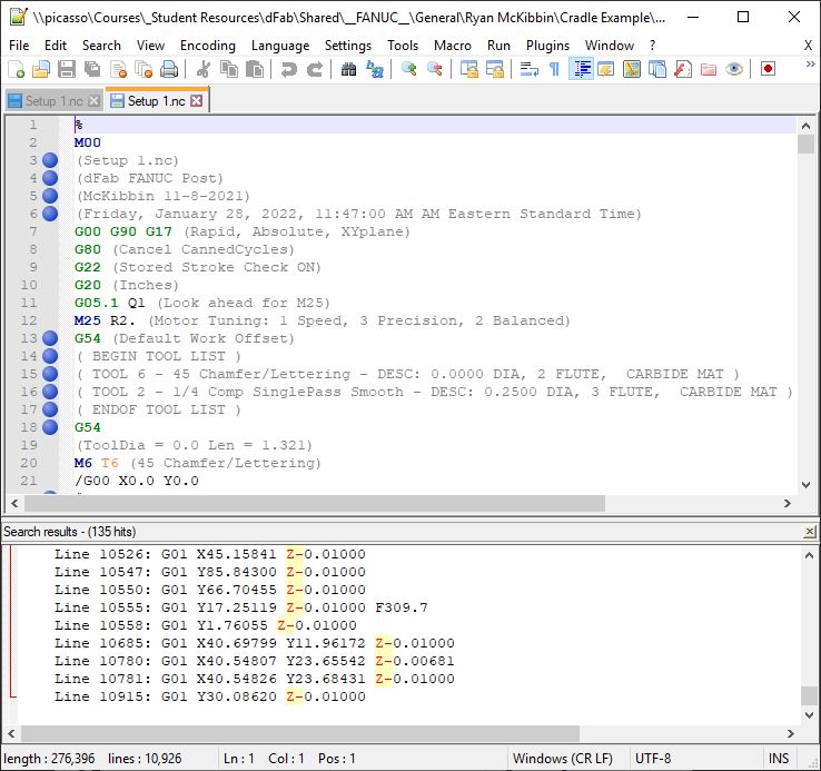
A docked search results panel will show all lines that match the search.
Verify that no values are below Z-0.010"
That's it, this file is ready to cut!
So we went out to make the cut, and realized that our plywood was warped! The vacuum can't hold it down, now what?
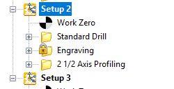
We need to screw the sheet down, but we need to know exactly where the screws are so we don't hit them with the tool. Screws are hardened steel, they can not be cut and will destroy our cutting tool. For the sake of argument (and so I can show you more stuff!) let's pretend that we noticed the vacuum issue after engraving the letters. We want to skip that toolpath in Setup 2.
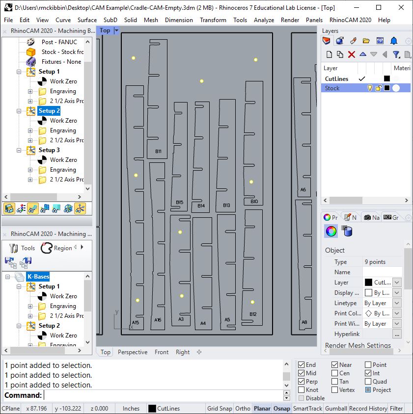
Back at the computer, we re-open the file and go to Setup 2 to draw in some points used for hold down locations. We observed generally where screws are needed at the machine and can place points logically. With the Project object snap on, place a few points on the XY plane as shown.
With the points selected, start a Standard Drilling cycle.
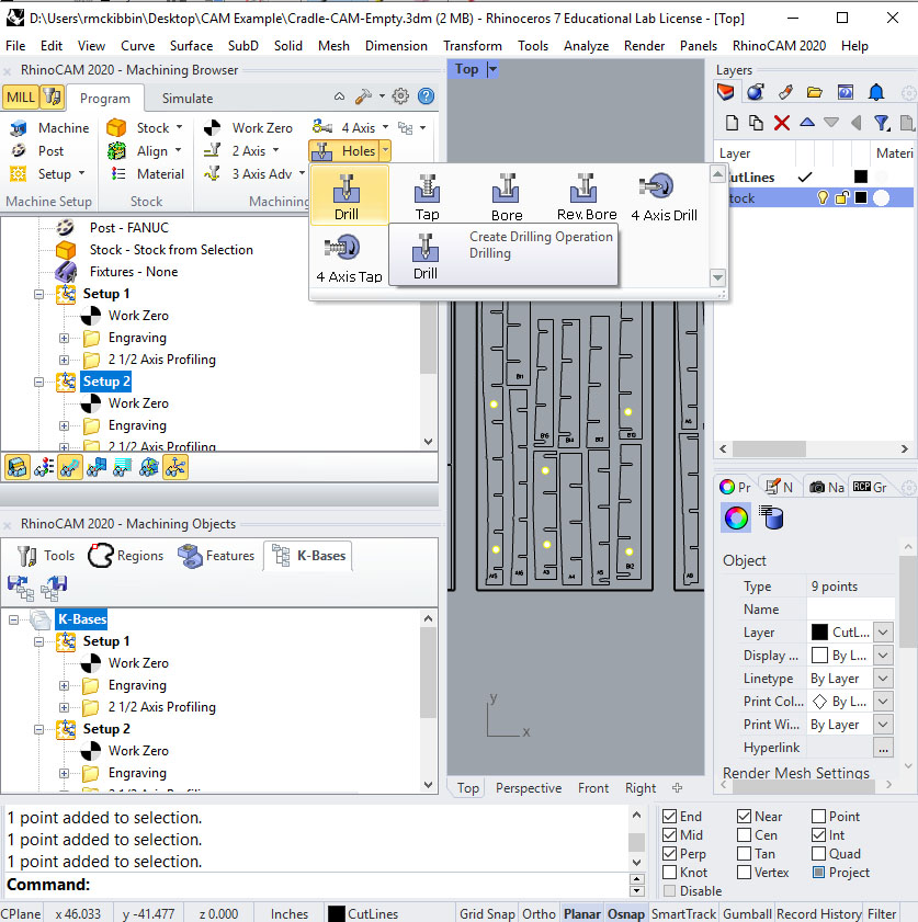
Because the points were pre-selected they are automatically recognized as Control Geometry by the toolpath when it is created.
Tool, Feeds & Speeds
Use the 1/8" Drill and load the Feeds and Speeds from the tool as described in previous sections.
Clearance Plane
If the plywood was really warped, it would be a good idea to adjust the clearance plane as shown below.
![]()
Cut Parameters
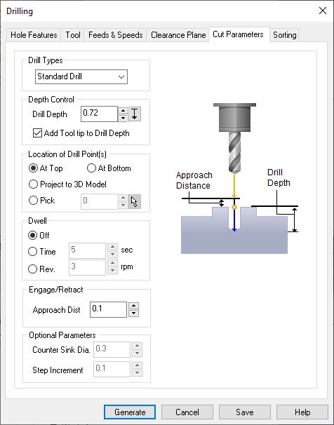
There are three drill types used in dFab. Most holes are made with Standard Drill. If a hole is deeper than 6x the tool diameter then Deep Drill is used.
When Deep Drilling, the tool will "peck" at the hole, removing the material in multiple motions and fully retracting the drill out of the hole between pecks.
Break Chip drilling is sometimes used on the Haas, this will retract the drill a small amount, but the drill will not be removed from the hole entirely.
The above settings are great for plywood with our established feeds and speeds. We break through 0.02" with a drill after adding the tool tip to the drill depth.
Generate the toolpath.
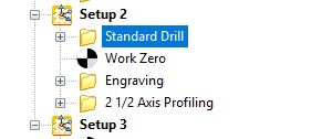
This toolpath is out of order! It can be moved by LMB click and drag.
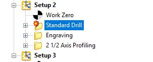
Since the toolpath was previously unaffected by the work zero (because it was above) we need to regenerate the Drilling toolpath.
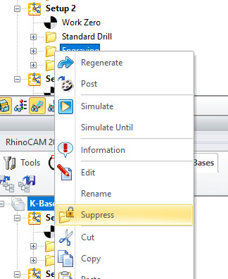
After regenerating the drilling toolpath, we want to ignore the engraving toolpath by LMB selecting the toolpath then RMB clicking. Choose Suppress from the context menu.
Now we are ready to re-post. We have saved the settings in the engrave toolpath, but it will not be executed.